
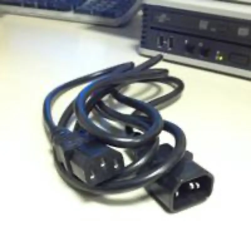
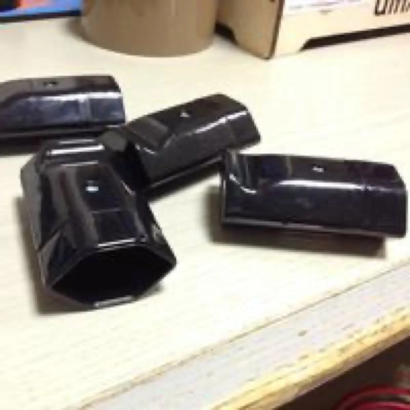
Every now and then in life you come across devices such as uninterruptible power supplies (UPSs) which deliver power not through the familiar Swiss mains plug but through the pin-laden partner of PC power cables, the C14 plug. Often you can only connect devices with PC power plugs there, because the only cables on sale have that same C14 plug on one side and the C13 plug you know from PCs and microwaves on the other.
At some online shops it is possible to buy adapters that let you connect normal power supplies with a Swiss plug to a PC power connector, but they happily cost CHF 25 or more. And that is without the power cable. So you can reckon on around CHF 34 just to be able to use the coffee machine during a power cut, for example, and so keep a cool head.
The resourceful maker knows another solution, though. All you need are the regular UPS power cables (C13 to C14), which can be found online for around CHF 9, and a couple of Swiss power sockets, available for CHF 1 at the DIY store.
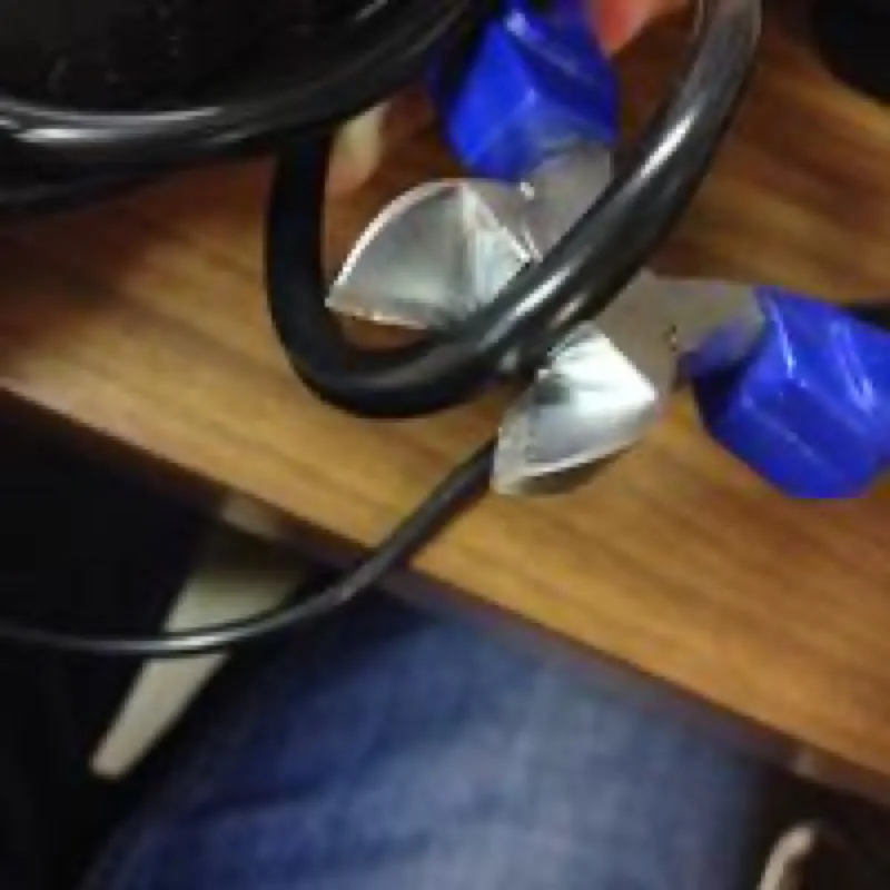
For the first step you need sturdy side cutters or a comparable tool. Use them to cut through the power cable. It is advisable not to cut directly at the plug but rather more towards the middle, so that you can fit the cable end with another power plug and go on using it. It is of course also important that the power cable is unplugged while cutting, since touching the 220 V of the local mains can lead not only to burns and the associated kidney and liver damage, but the energy suddenly passing through could also melt the side cutters.
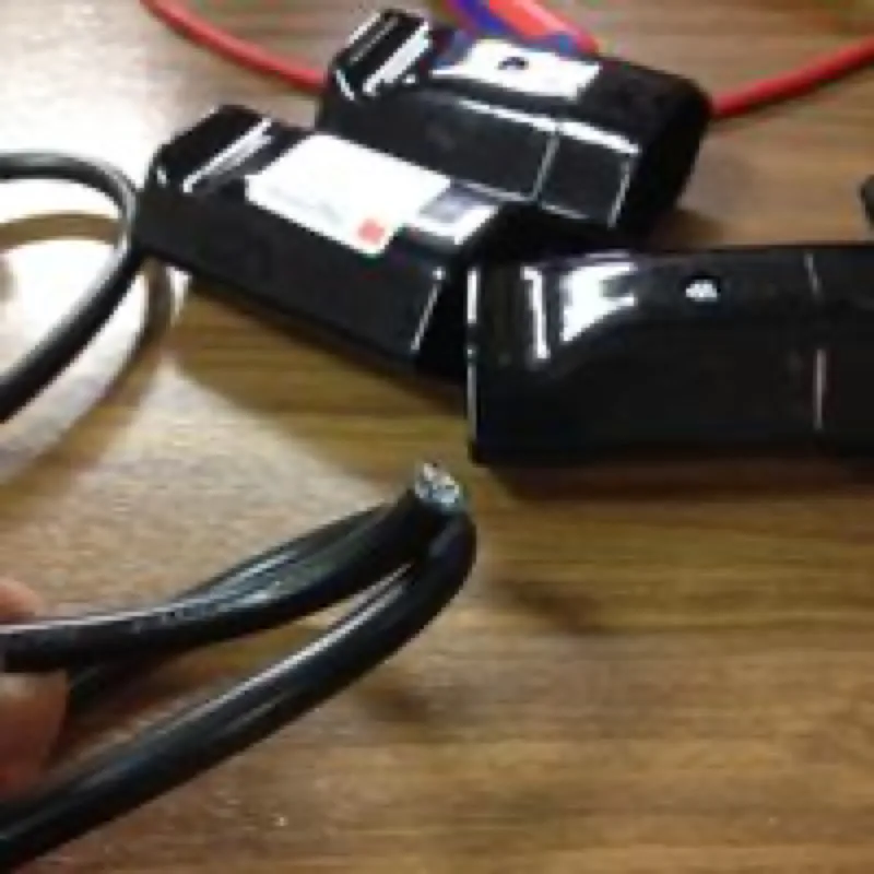
Now you can see clearly how the power cable is built. It consists of three wires, which are in turn made up of many small individual strands. This construction is called stranded wire. The individual conductors have to be very strong, that is, made of many individual strands, so they do not melt when large currents flow through the cable.
The three conductors are distinguished by colour, since they have different functions in the power cable. They are separated from one another by an insulating plastic sheath. The colour of the plastic sheath indicates the function of the respective conductor.
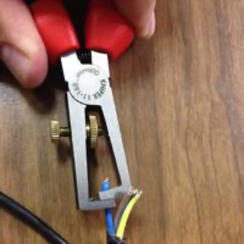
Since the cable does not fit into the new plug as a whole, complete with insulation, the next step is to remove about 2–3 centimetres of the outer black insulation with a wire stripper. If you remove too much, the cable unfortunately does not hold properly in the plug (because the fastening works by clamping the outer black insulating layer). That is relatively easy to remedy, though, by shortening the protruding conductors a little (or winding more of them around the contacts — more on that later).
Some may be tempted, lacking a wire stripper, to use a pocket knife. That is inadvisable for several reasons. Usually you cut through not only the outer insulating layer with the pocket knife but the inner one too, which increases the risk of unwanted contacts. That is not exactly pleasant at 220 V and can have fatal consequences. There is also the danger that the blade of the pocket knife cuts into the conductor and blunts itself in the process. Furthermore the stranded wire can be thinned at that point by severing some of the small strands. That makes the wire hotter at that point, leading to a risk of melting and fire. A wire stripper is, by comparison, quite cheap and versatile.
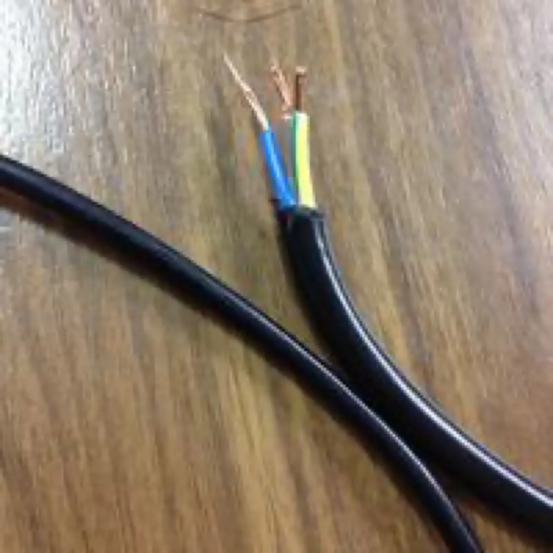
Now the tips on the cable side just need to be stripped a little. To do this, carefully remove the insulation over roughly the width of a screw head with the stripper.
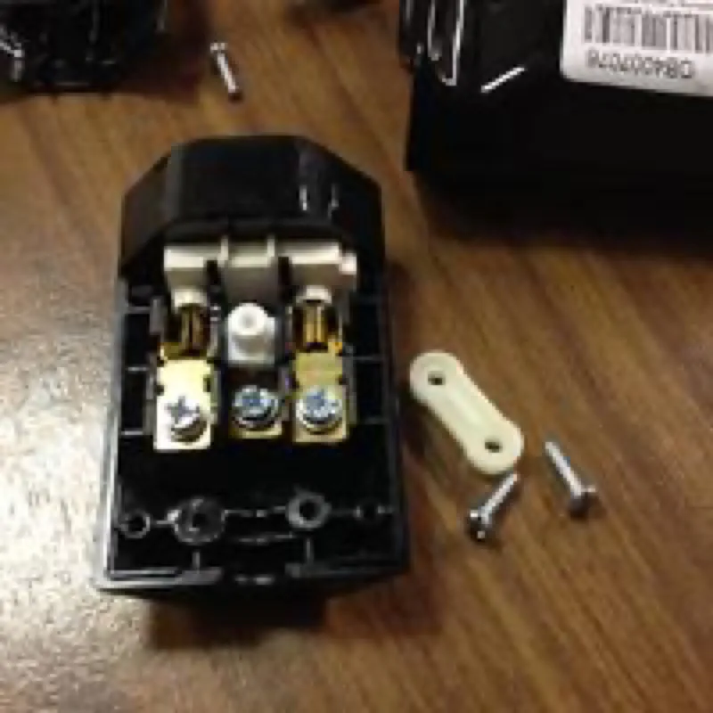
Now we turn to the type 13 coupler. First the screws at the end have to be loosened, so that the cable can be fastened by its thick insulation.
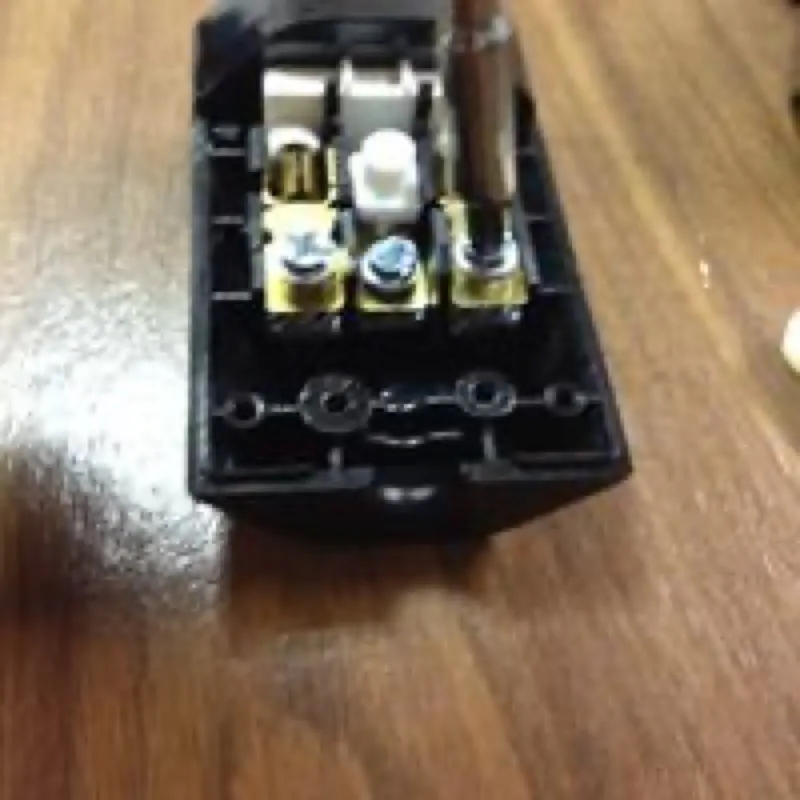
Now the contacts have to be “opened”, so to speak. There are usually screws for this which press a metal plate against the contact. We have to loosen these in order to fasten the conductors in them afterwards.
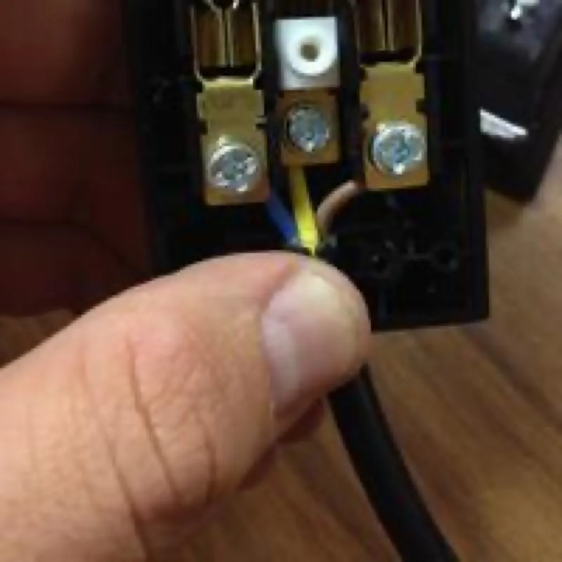
Now the conductors have to be connected to the actual contact. To do this, the conductor is pushed between the metal plate and the top of the contact with the screw (not on top of it — the screw alone does not hold the conductors apart well enough and can also get very hot as a result). That can turn out a bit fiddly, but it is basically doable.
What matters here is the arrangement of the three conductors by their colour (or that of their insulation). It is quite simple: the brown conductor goes on the right. The yellow-green striped conductor goes at the bottom in the middle. The blue conductor goes on the left. So just remember: brown — right. The rest follows by itself.
Once the conductors are in place, the screws that are supposed to hold them should be tightened again, to clamp the conductors and make the contact.
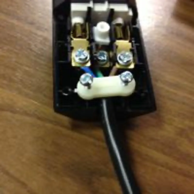
So that the tensile load of the power cable does not hang on the contacts and the small conductors alone, the white strain relief bridge now has to be screwed back in at the entry of the socket. It is important here that the strain relief clamps the thick black insulating layer of the cable and not the three thin coloured conductor insulations. That makes the plug more stable and longer-lasting.
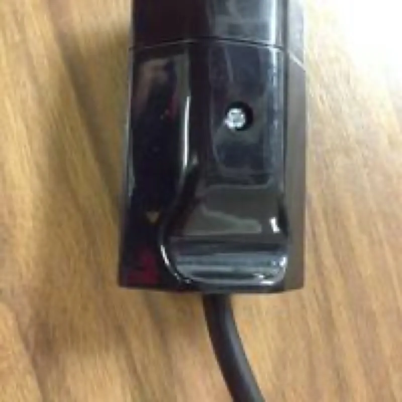
Now the cap just has to be put back on, so that the contacts cannot be touched (220 volts is quite a lot and does not exactly aid relaxation). It is held in place by a single screw.
Testing
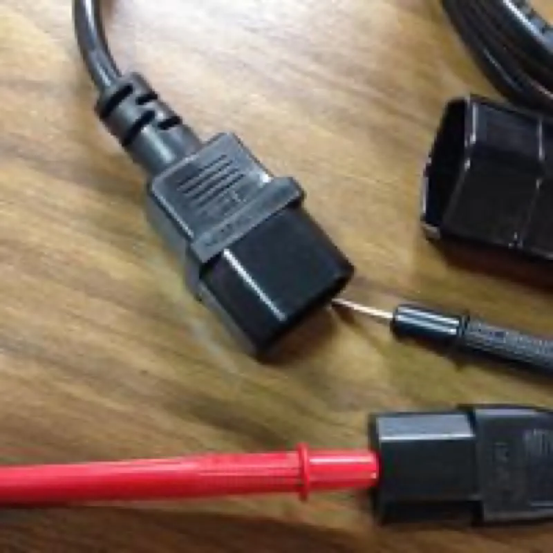
You could now plug the finished cable in somewhere straight away. But as already mentioned, 220 volts is not a voltage to joke with. So before putting the power cable into service, you should carry out a few more checks. Otherwise short circuits, fires or life-threatening electric shocks can result. And who wants that?
Ideally you use a multimeter for this. The easiest way is to use the continuity mode. It indicates with a beep whether current can flow between the points at which you have placed the two probes. But you can also simply use the resistance measuring function (Ω): a finite resistance then indicates that there is a connection between the two points.
The one important point is of course that current can flow between the connected contacts in the type 13 socket and the C14 plug (the device beeps or shows a finite resistance). If all three contacts are connected to the corresponding contact on the opposite side (left → left, middle → middle, right → right), the cable is able to conduct electricity.
The greatest enemy of the electronics maker, though, is connections that should not be there. Since the stranded cable consists of many small strands, it is not far-fetched that one of them might not be screwed down properly at the contact but instead make a connection with one of the other contacts. That is very dangerous and leads to short circuits and fires. So you should now also make sure with the multimeter that the contacts are not connected to one another. This applies to both sides, so no finite resistance should be measurable between any of the three contacts on the plug, and the multimeter should not beep.
It is also important that there is a large enough contact area between the conductor ends and the contact plate. Unfortunately that cannot be measured so precisely. Not too many strands should have been lost from the conductors either, since otherwise more current flows through a smaller cross-section and the plug heats up strongly and can burn through, melt or catch fire. Unfortunately that is likewise not easy to establish with a multimeter, so see the notes on the subject in the assembly instructions.
If all this is the case, the cable is basically ready for use. You can now plug it into the UPS and connect a device with a normal mains plug. Congratulations!